Inclined-Manometer Pitot Flowmeter
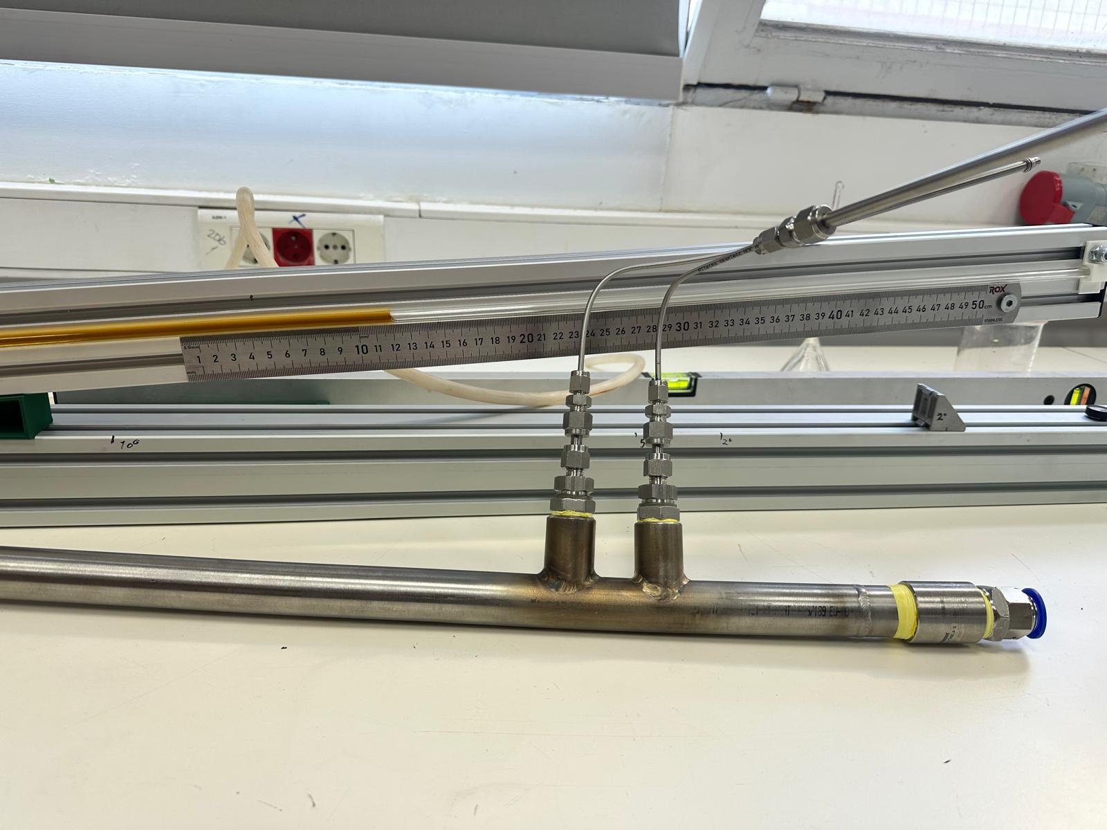
A Pitot-tube air flowmeter built from simple parts: the dynamic pressure at the pipe centre is read on an inclined liquid manometer whose angle can be set precisely with 3D-printed wedges.
- Range
- about 10–100 Nm³/h of air
- Principle
- Pitot tube, dynamic pressure at the centre line
- Readout
- Two 1 m glass or clear tubes as an inclined manometer
- Angle setting
- 3D-printed triangular wedges
- Calculator
- Pitot tube flow
A Pitot tube measures flow with a very simple piece of theory: it compares the total pressure at the tip, facing the flow at the pipe centre, with the static pressure of the stream. The difference is the dynamic pressure ½ρv², so the centre-line velocity follows from its square root, and the volume flow from the ratio of mean to centre-line velocity (Bird et al., 2002, Eq. 5.1-5; ISO 3966, 2008). To keep the cost down, the reference (static) pressure can be taken at a point a little away from the tube itself.
Reading small pressures precisely
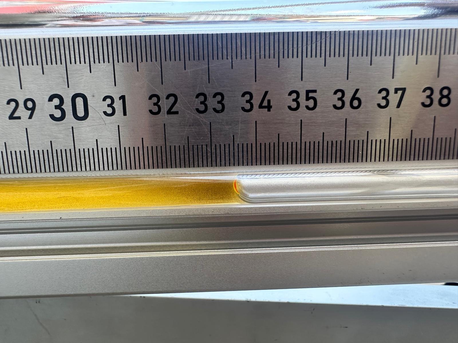
Gas dynamic pressures are small, so they are read on a liquid manometer that can be tilted. At an angle θ the liquid moves a length L = Δp/(ρl g sin θ) along the tube, so a shallow angle stretches a tiny pressure difference over a long, easily read length. Two glass or clear tubes of 1 m give a very wide range depending on the pipe diameter. To set the angle accurately I printed triangular wedges on a 3D printer: printed parts are dimensionally far better than low-cost angle gauges, so the angle, and with it the calibration, is known more precisely. With these simple parts the meter measures air flows of about 10–100 Nm³/h.
Tappings and entrance length
The reference pressure is taken upstream of the Pitot tube. The welded fitting looks large compared with the pipe, but the hole into the flow is very small. The straight inlet length of the pipe was also increased so that the velocity profile is fully developed at the probe and entrance effects do not bias the reading.
References
- Bird, R. B., Stewart, W. E., & Lightfoot, E. N. (2002). Transport Phenomena (2nd ed.). Wiley, New York.
- ISO (2008). ISO 3966: Measurement of fluid flow in closed conduits — Velocity area method using Pitot static tubes. International Organization for Standardization, Geneva.