B3 Liquid Rocket Feed System
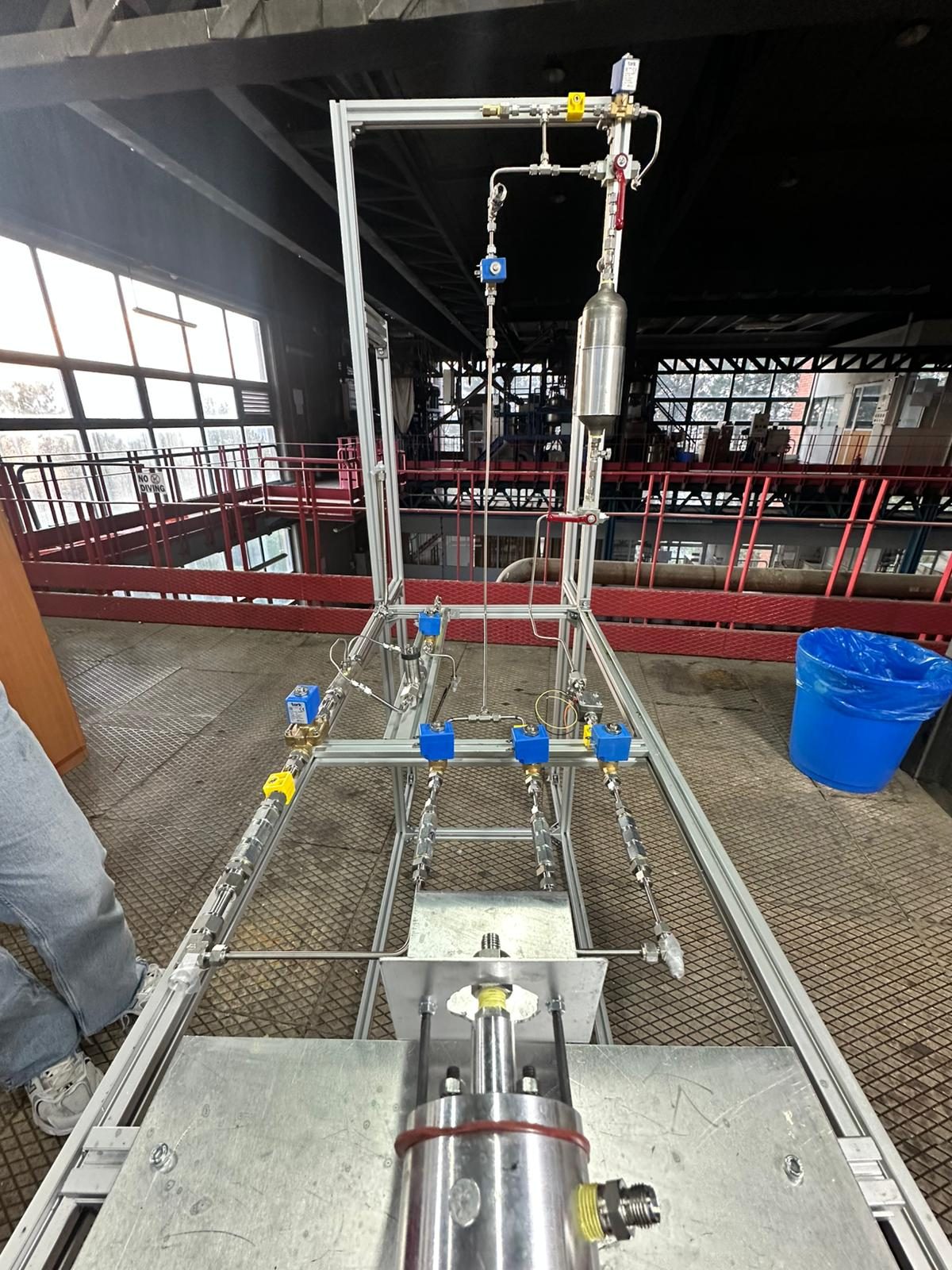
A pressure-fed propellant system for a 100 N gaseous-oxygen / Jet A-1 rocket engine, built by a student team to compete in the B3 category of Teknofest.
- Application
- Liquid rocket engine test stand, Teknofest B3 category
- Propellants
- Gaseous oxygen (GOX) + Jet A-1
- Engine thrust
- 100 N
- Operating pressure
- 20 bar
- Pressurant / purge
- Nitrogen
- Modelling
- MATLAB Simscape — transient flow & pressure
Teknofest is Türkiye's national technology festival, and its B3 category challenges student teams to design and fire their own liquid-propellant rocket engine. Our job was the part that nobody sees but everything depends on: the feed system that delivers oxidiser and fuel to the engine at exactly the right pressure and flow.
The engine burns gaseous oxygen with Jet A-1 and produces around 100 N of thrust. The hardest engineering problem in a system like this is not getting propellant to the engine — it is keeping the combustion stable. Pressure oscillations in the chamber can couple back into the feed lines, so the pressure drop across the liquid injector has to be calculated carefully to isolate the tanks from the chamber (Sutton & Biblarz, 2017, Ch. 9; Huzel & Huang, 1992, Ch. 4).
Design
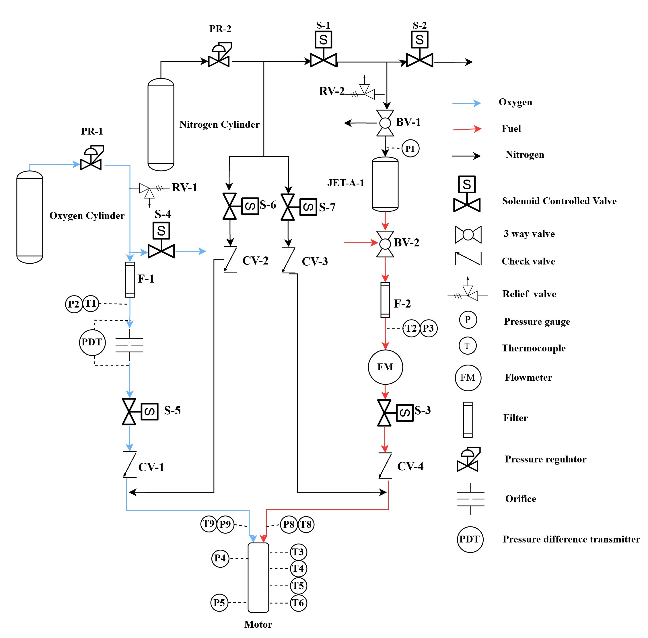
Because the system runs at 20 bar, leak-tightness was a first-class requirement, not an afterthought. To keep the fuel pressure constant throughout the burn, the Jet A-1 tank is pressurised with nitrogen. The same nitrogen doubles as a safety system: when the timed firing ends, nitrogen is routed into the engine to purge the lines and extinguish combustion cleanly.
The diagram above shows the baseline concept. The final design went further, adding stepper-driven needle valves for fine control of pressure and flow, and a flame arrestor on the oxygen line to improve safety.
Dynamic model
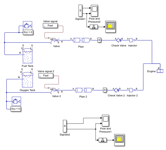
Before building, the feed lines, valves, injectors and a pressure model of the engine were assembled into a dynamic Simscape model. This let us study how flow and pressure evolve over time — valve opening, start-up transients, and shutdown — instead of relying on steady-state numbers alone. The final model is considerably more detailed and includes every component on the stand.
References
- Huzel, D. K., & Huang, D. H. (1992). Modern Engineering for Design of Liquid-Propellant Rocket Engines. AIAA, Washington, DC (Progress in Astronautics and Aeronautics, Vol. 147).
- Sutton, G. P., & Biblarz, O. (2017). Rocket Propulsion Elements (9th ed.). Wiley, Hoboken, NJ.